This is a brief article about when you can rely on the DAC calibrations on the SLab system.
If you see the CurveVV command in the DC module that is used to obtain a DC voltage transfer curve of a Circuit Under Test (CUT), you will notice that you can use the basic configuration that uses DAC1 and ADC1:
Or a configuration that uses DAC1, ADC1 and ADC2:
If the DAC1 operation has ben properly calibrated, you may ask why do you need to take measurements on Vi using ADC2.
Well, the truth is that you cannot always rely on the DAC calibrations because they can depend on the load applied to their nodes. If you recall the DAC driver circuits, they are based on follower opamps or non inverting amplifiers.
Opamps have limited current capabilities. This doesn't affect to the ADCs because no current is drawn on the ADC nodes, but you can put any load on the DAC nodes and the opamps won't alway be able to cope with it.
The following figure shows a test circuit for the DAC output load capabilities. DAC 1 is connected to ADC1 and a grounded resistor R.
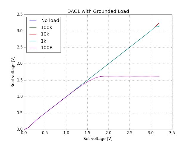
The following figure shows the ADC readings as function of the DAC values set for different values of the resistor R. You can see that the programmed DAC value gives the proper voltage to the node for resistances of 10k or more. For lower loads there is a degradation that increases at higher voltages. For a 100 Ohm load, the voltage is only good up to about 1.5 Volt with some degradation before reaching this point.
Is this behavior expected? Well, the MCP6002 opamp datasheet shows the following maximum short circuit currents:
At 3.3V and 25ºC the short circuit current is about 15 mA. For a 100 Ohm load that meas that the maximum voltage will be 1.5 V. This is the result shown on the measurement curves.
For a 1k resistor, the voltage limit should be 15 V, but we see some degradation before reaching the 3.3V limit. Why is that?
The limit in this case is the voltage headroom. The MCP6002 is a full rail opamp. That means that it should de capable to reach both supply rails. In practice, however, no opamp can be really full rail. You need some voltage difference between the output and the rails to maintain the output current. This minimum voltage difference to the rails is the Headroom voltage. The following figure, taken from the opamp datasheet shows the needed voltage to the rails as function of the current.
In our case, to reach 3.3V using a 1k resistor, we need to provide 3.3mA. From the above curve we can see that we need a headroom of about 100 mV to maintain this current. So we cannot get above 3.2V and that's about what we are seeing in our measurements.
The same experiment can be performed for loads connected to Vdd.
For a specified 15 mA short circuit current the maximum voltage drop to Vcc will be 1.5 V on a 100 Ohm load. As Vdd is 3.3 V, that gives a voltage of 1.8 V minimum voltage respect to ground. Just about the limit we are measuring.
The headroom voltage also explains why we cannot reach the 0V limit with a 1k load.
The headroom voltage also explains why we cannot reach the 0V limit with a 1k load.
That's all for this article. When you driving voltages using SLab or any other instrument like a power supply or a function generator, there are always limits to the load you can put on the driven node.
If you are not sure that the node can be properly driven, it is a good idea to measure the REAL voltage value on the node instead of relying on the voltage selected on the instrument.
In the particular case of the CurveVV command, using ADC 2 on the node driven by DAC 1 guarantees that the final curves you obtain relate the REAL voltage input to the output voltage on the circuit.
In the particular case of the CurveVV command, using ADC 2 on the node driven by DAC 1 guarantees that the final curves you obtain relate the REAL voltage input to the output voltage on the circuit.


No comments:
Post a Comment